
(An animated sequnece illustrating the following process is available on our Movies Page. For those with less bandwidth there is also the slide show)
The mirror will be transported from Earth to low Earth orbit in a compact circular network of wires wrapped around an SPS microwave transmitter. Using its orbital motion this wire network will extend through rotation and in the process provide a frame for the attached paper-thin sodium foils, constituting the reflective surface area of the mirror (ref. 50). The mirror will be fully extended (frame measuring 3.014km in diameter, with a total reflective surface area of 3.846km2 found on the circumference to a depth of 424m and from a radius of 156.9m to 256.9m – see fig. 2.2e) after four months and will then be transported, using solar sails (see 5.1 External Transport System), to L4 where the solar cells will be made and fitted to the remaining free frame area.
Initial construction of the settlement will also take place in low Earth orbit. This will allow the heavy equipment and materials necessary for building the torus and spokes to be put in place relatively cheaply and efficiently (see fig. 3.2a) early on.
 |
DaedalusaL4’s spherical centre will be the first step in construction and act as a ‘safe-house’ for construction workers. An inflatable sphere, composed of an outer layer of intertwined aluminium wires and inner multilayers of aluminised Mylar and Kapton insulation blankets, will be transported to the site from Earth and inflated from the transporting craft. Measuring 600m in diameter the sphere will have two ‘hubs’ attached tangentially to it on opposing ‘sides’. The upper, mirror side hub will house a robotic arm, used to spray the interior with the metals, aluminium and copper-tungsten alloy (using the xenon electrolytic process detailed in 2.2 Torus - shielding). This hub will later be redesigned to accommodate the rectifying antenna and some thermal radiator equipment. Once this ‘rigidisation’ has taken place, there should be sufficient, if limited, radiation protection for construction crew to enter the sphere’s interior, with only a limited atmosphere, and install a pedestal structure around the internal surface area. This will act as a support for the second inflatable sphere, which will then be deployed from the second lower hub, later to be converted into the docking facilities. The second inflatable will have a radius approximately 1.5m less than the first and will be rigidised in a similar manner (ref. 12).
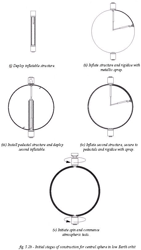 |
Once water has been installed in the substructure
cavity (between the two inflatables), forming an ice shell for structural rigidity
and radiation protection, atmospheric and spin tests can commence (see fig.
3.2b). This will enable a minimal atmosphere, transported from the Earth,
containing normal O2 and CO2 levels but half the terrestrial
sea-level concentration of N2 to be installed. During construction
spin will be set to 2rpm, rotating about the axis drawn between the two hubs,
approximately normal to the equatorial plane. This rotational rate will allow
a simulated gravity of 1g at the internal diameter of the sphere. With an atmosphere
present it will now be possible to allow exposure of the workers to the interior
while the oxygen and ore extraction equipment is installed. It will now also
be possible to convert the lower hub into docking facilities with its circular
base 111.7m from the sphere’s centre (see fig. 7.1a) – giving it a gravity
of about ½g. Meanwhile the upper hub can be used as a rectifying antenna but
also as an excess heat radiator.
At this point the fledgling settlement will be transported to L4 using a tether infrastructure (see 5.1 External Transport System). Once in position its axis of rotation will again be approximately aligned normally to the equatorial plane with the mirror being put in place at an angle 45° to this, thus reflecting light down to where the torus will be located. Once spin of the sphere has recommenced ore extraction and solar panel production can take place in the central sphere. This will enable the remaining frame to be covered with solar cells and connected to the previously installed transmitter so that power can be beamed to the settlements newly constructed rectifying antenna.
Meanwhile, on board the sphere, four additional (smaller) hubs will be attached normally to the axis of rotation, equidistant from each other along the sphere’s diameter. These hubs will provide access ports to four additional inflatable spheres, each similar to the central sphere (with two inflatables and an ice filled substructure 1.5m thick) except only measuring 50m in diameter. Once these are inflated four tubes, measuring 10.5m in diameter will be constructed through their centres, normal to the axis of rotation of the central sphere, using aluminium plate and ribs. These tubes will provide ‘sleeves’ for the 10m diameter spokes which will be constructed, again using aluminium plate and ribs, through the centre of the initial tubes.
This system allows for the use of the small spheres as radiation shelters for the workers while external construction of the spokes takes place. The spheres will be capable of movement up and down the spokes, both during construction and later during the lifetime of DL4, thanks to electromagnetic induction linear motors acting in opposition to the aluminium spokes, running through the ‘sleeves’ of the spheres. On the inside of the spokes workers will be protected using a movable end cap that will slowly advance down towards the torus. Docking capabilities between the movable spheres’ ‘sleeves’ and the spokes will be allowed for every 18m (from base of one access port to the base of the next) for the spokes 515.9m (from the central sphere to the outer wall of the torus) length. Both oppositely aligned pairs of spokes must be constructed at an equal rate to ensure that the spin of the settlement is not affected.
During this time, internal life support and waste removal systems will be installed for all completed sections; some of the central sphere will be given over to agriculture to allow crops to be tested; sufficient atmospheric gases will be produced (O2) or supplied (N2) to bring all areas to the final correct atmospheric composition and spin should be slowed down to its correct value of 0.975rpm. This will provide a near 1g gravity level for the workers constructing the torus and a 0.32g level for those constructing the heavy industry sections within the central sphere.
Once the radius of the torus floor, found at 940.9m from the centre of DL4 (815.9m from the outer wall of the central sphere), is reached by the spokes, four small curved areas of this floor, each measuring 625,000m2, will be extended from the base of the spokes. This will enlarge the torus shell to its own internal radius of 125m. Unfortunately no major protection can be achieved for the builders at this point so, as far as possible, all segments must be constructed in the central sphere and transported, through the docking facilities, to the outer rim. This way the aluminium ribs of the torus can be constructed, for want of a better expression, like a jigsaw puzzle. Once this is complete the torus can be coated with a ‘stretched skin’ of aluminium and aluminised Mylar and Kapton, covered with the Trans-Hab Meteorite Shielding, which will be inflated once in place. This ‘coating’ process will commence on the inner (towards the central sphere) underside (non-mirror side) of DL4 and work outwards towards the 515.9m level of the torus floor. This underside will incorporate internal regolith/polyamide radiation shielding (see fig. 2.2d), although water will not be added to any such shield until the settlement is sealed off (to prevent water evaporation into space).
While this ‘roof’ is being added to the torus, on the underside of the floor the external radiation shield (see fig. 2.2d) must be constructed, while that area of the torus still consists of aluminium rib ‘scaffold’. Again, this regolith will be transported to the site from the central sphere and there coagulated in a ring enveloping the outer rim. Once this is completed the coating of the remainder of the torus surface area can be completed as above, except above floor level on the upper (mirror) side. This area must incorporate the lead-glass windows (as detailed in 2.2 Torus - lighting) with one large pane per habitation segment (8 in total – see Internal Design). The lead required for such glass production represents the one large mass (apart from 10,000 people!) material that will be transported from Earth. Lunar glass, infused with lead, will be produced within the central sphere and then moved to the window section of the torus.
Once this is complete, an atmosphere can be released to test for air-tightness and, all going well, extension of the floor from the previous 625,000m2 areas can be commenced in shirt sleeve conditions. During construction of the floor, providing correct atmospheric levels have been reached, internal structures should be gradually constructed. Specifically, agriculture should move from the now low g levels (0.32g) of the central sphere to the normal gravity level of the torus and production of the first harvest should begin. To balance this, all life support systems should be operational. After water reserves have been transported from production in the central sphere, through the spokes to reservoirs beneath the torus floor, the torus should be populated.
Within the central sphere, construction of the heavy industries on the inner circumference should be complete while the spokes are extended to a new mini-central sphere (inflated and padded in the exact centre of DL4, providing a micro-g research and recreation area) and other details of the design are completed (see fig. 7.1a). These will include the incorporation of a window, of similar lead configuration to the torus windows, in the central sphere (an observation deck with clear glass has also been provided, see fig. 7.1a). The glass segments for this window will be manufactured in the central sphere and placed in the correct positions around the interior. Here, they can be sealed in place, while externally the Mylar/Kapton and the ice sub-structure are removed, revealing the window.
Meanwhile the moveable spheres will have been converted for their role in variable g scientific research, having floors added and the necessary pieces of equipment installed.